Computer Architecture: A Quantitative Approach
This is my notes on the book Computer Architecture: A Quantitative Approach by John Hennessy and David Patterson. I am reading it out-of-order thought the notes will be committed in-order. (forgive my lame joke)
Chapter 5 Memory Hierarchy Design
Intro
The gap between processor and memory performance grew increasingly large → motivates memory hierarchy so that quicker but smaller caches act as intermediaries
Set Associative: a memory block is mapped onto a set, and then the block can be placed anywhere within that set. n-way set associative: n blocks in a set direct-mapped cache: one block per set (n=1) fully-associative cache: one set (n=# of slots in cache)
Advanced Optimizations of Cache Performance
Hardware Prefetching
Since memory is a hierarchy, often times the instruction or data we needed are not in L1 caches – they may reside in lower caches or even main memory. When we do not care about performance and wait for an instruction and data to be fetched exactly when it’s needed, this is called demand-fetch. To optimize performance, we prefetch data/instruction into caches.
Instruction prefetch is frequently done in hardware. On a miss, processor fetches the requested block as well as the next consecutive block. Requested block is put into the instruction cache, the prefetched block is put into instruction stream buffer.
Prefetching and branch prediction are both speculation. But prefetching does not impact correctness, it improves performance (by improving cache hit rate), whereas wrong branch prediction lead to incorrect program.
Software Prefetching (Compiler-Controlled)
Two ways of software prefetching
- Register prefetch (hoisting/binding): load the prefetched value into a register
- may prevent instructions from committing
- Cache prefetch: loads the data into cache - require ISA support - may get evicted from cache before demand → futile work Either of the two ways can be faulting or nonfaulting. Faulting means that the instruction could incur virtual address checks, access right
Appendix - Pipelining
Three classes of instructions
- ALU instructions - take 2 registers or 1 register and a sign-extended immediate, calculate them, and store them into a third register
- Load & Store - calculate the effective address from the base register and the offset
- Branches and jumps - Comparisons between a pair of registers or between a register and zero
Five Stages of Pipeline
- Instruction Fetch Cycle (IF)
- Fetch the current instruction (stored in PC) from memory, increment the PC by adding 4 bytes (length of a instruction) to PC
- Instruction decode/register fetch cycle (ID)
- decode the instruction and read the source registers from register file
- fixed-field decoding: decoding is done in parallel with reading registers
- Execution/effective address cycle (EX)
- Depending on the instruction type, ALU performs one of the following
- Memory reference: adds the base register and the offset → effective address
- Register-Register instruction: perform operation (specified opcode) on the values
- Register-Immediate instruction: perform operation (specified opcode) on the value and the sign-extended immediate
- Depending on the instruction type, ALU performs one of the following
- Memory access (MEM)
- read from/write to the memory depending on load/store instruction
- Writeback cycle (WB)
- write the result into the register file, whether it comes from the memory (
load) or from the ALU (ALU instruction)
- write the result into the register file, whether it comes from the memory (
From sequential to pipelining
We could overlap different instructions to speedup the CPU execution. There are a few observations
- Separate instruction and data caches so that I-Cache and D-Cache can be accessed by different instructions at their decode (ID) and memory (MEM) pipe-stages respectively. This is why L1 cache usually have separate instruction and data caches.
- Two reads and one write to register file per cycle: two register reads in decode (ID) stage and one write in writeback (WB) stage. To handle read & write to the same register, register write in the first half of the clock cycle and the read in the second half.
- Need to update PC in decode (ID) stage, but might need to jump because of a branch being handled at decode (ID) stage.
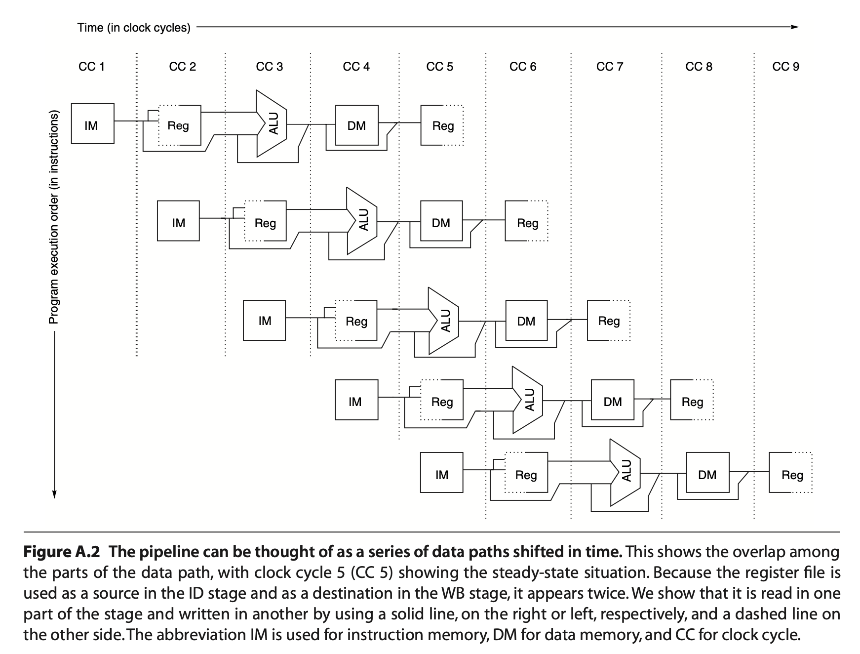
Pipeline registers to ensure isolation between different instructions: they save the results of a stage and used as the input for the next stage.
Issues with pipelining
- imbalance among the pipe stages
- clock can run no faster than the slowest pipeline stage
- pipeline overhead
- pipeline register delay: setup time; propagation delay
- clock skew: maximum delay between the clock arrives at any two registers
Pipeline Hazards
- Structural hazards: hardware unable to support all combination of instructions
- Data hazards: data dependencies
- Control Hazards: branches
To handle these hazards, we need to stall the pipeline, i.e. delaying all other instructions in the pipeline except for the one
Structural Hazards
When some of the resources cannot support the needs of pipelined instructions
e.g. single-memory pipeline → decode and memory stage both reads from the memory
pipeline bubble: stall the pipeline for 1 clock cycle
Provide separate memory access for instructions, by splitting the cache into instruction cache and data caches, or by using instruction buffers to hold instructions
Data Hazards
When the instructions have data dependencies and pipeline changes the order of read/write accesses
Forwarding (bypassing)
- ALU result from both the EX/MEM and MEM/WB pipeline registers is fed back to the ALU inputs
- If the forwarding hardware detects the previous ALU operation has written source register for the current ALU operation, control signals selects the forwarded as the ALU input
Forwarding sends the data from the output of any functional unit to another
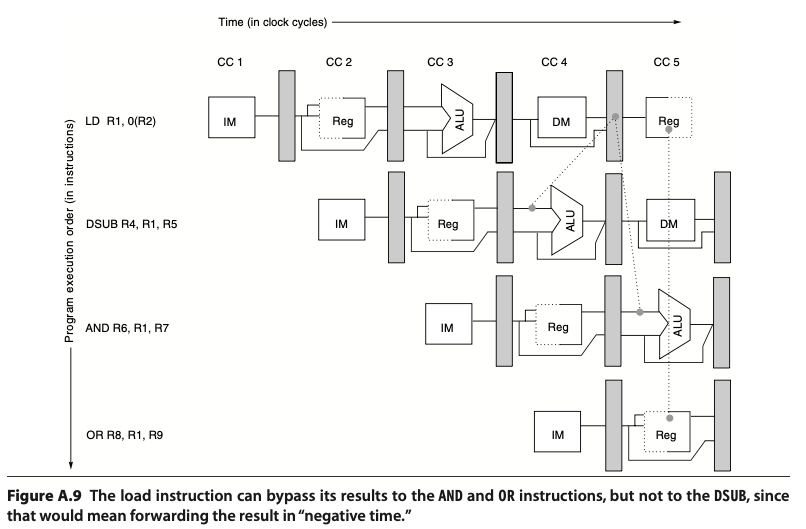
However, not all data hazards can be handled by bypassing e.g. a memory (LD) operation followed by a ALU operation (DSUB) that requires the LD result. The LD operation have the data ready at the end the MEM stage (end of CC4), whereas the DSUB requires it in EX stage (beginning of CC4). In this case, we introduce pipeline interlock, to preserve the correct execution pattern by adding bubbles.
Branch Hazards
When a branch is executed, it may or may not increment the PC by 4. A branch instruction that gets taken normally change the PC at the end of ID (decode) stage.
Reducing Pipeline Branch Penalties
Suppose we have a branch instruction . If the branch is not taken, we execute the next instruction and so on. If the branch is taken, we jump to branch target and execute and so on.
- freeze or flush the pipeline: fetch the instruction again only after the decode (ID) stage of branch instruction → causes a 1-cycle stall. First fetch (IF) is essentially a stall.
- predicted-not-taken or predicted-untaken: always presume the branch is not taken and fetch the instruction . If the prediction is wrong, then change the later stages (ID, EX, MEM, WB) to
no-opand fetch the branch target instruction .- predicted-taken does not work in MIPS since branch target is not known until after the decode (ID) stage; other processors might be able to predict taken.
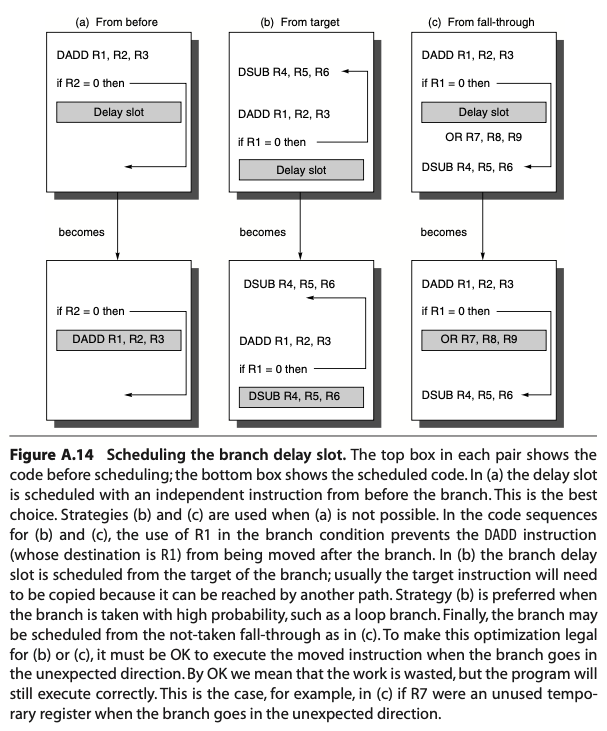
- delayed branch: execute instruction (the sequential successor) in the branch delay slot. Then after the instruction is done with decode stage (CC3), we execute instruction if the branch is not taken and execute branch target if the branch is taken.
- We could fill the branch delay slot with an instruction from before in scenario (a). This is the ideal situation
- We could fetch the predicted-taken instruction in scenario (b), if wrong, the instruction in the branch delay slot is turned into a no-op.
- We could fetch the predicted-untaken instruction in scenario (c), if wrong, the instruction is turned into a no-op
Pipeline Implementation
- Instruction fetch cycle (IF)
- Instruction Register (IR) holds the instruction that’s being executed, fetched from memory using address stored in PC, i.e.
IR <- Mem[PC] - NPC holds the address of the next sequential instruction, i.e.
NPC <- PC+4
- Instruction Register (IR) holds the instruction that’s being executed, fetched from memory using address stored in PC, i.e.
- Instruction decode/register fetch cycle (ID)
- Read register file and store them into two temp registers
A <- Regs[rs]B <- Regs[rt]
- Read the lower 16 bits of IR and sign extend it to store in the the temp reg
Imm <- IR[15:0]
- Read register file and store them into two temp registers
- Execution/effective address cycle (EX)
- Memory reference: form the effective address
ALUOutput <- A + Imm
- Reg-Reg ALU instruction: performs the operation specified by the function code
ALUOutput <- A func B
- Reg-Imm ALU instruction: performs the operation specified by the opcode
ALUOutput <- A op Imm
- Branch: ALU adds the NPC to the sign-extended immediate to compute the branch target address
ALUOutput <- NPC + (IMM << 2): shifted left by 2 bits to create a word offsetCond <- (A == 0): comparison against 0 forBEQZ
- Memory reference: form the effective address
- Memory access/branch completion cycle (MEM)
PC <- NPC- Memory reference: load/store based on the address computed by ALU in prior cycle
LMD <- Mem[ALUOutput]: load into LMD (load memory data) registerMem[ALUOutput] <- B: store B register into the address
- Write-back cycle (WB)
- Write back into the register file
- Reg-Reg ALU
Regs[rd] <- ALUOutput
- Reg-Imm ALU
Regs[rt] <- ALUOutput
- Load instruction
Regs[rt] <- LMD